- 您现在的位置:买卖IC网 > Sheet目录1991 > CS4341A-KSZ (Cirrus Logic Inc)IC DAC STER 24BIT 192KHZ 16SOIC
CS4341A
30
DS582F2
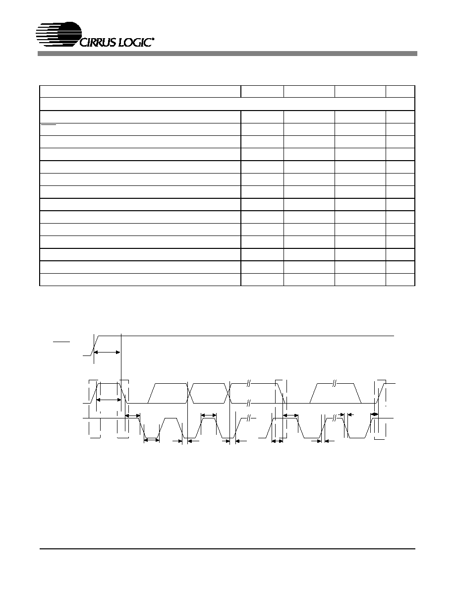
SWITCHING SPECIFICATIONS - CONTROL PORT INTERFACE
(Inputs: Logic 0 = AGND, Logic 1 = VA)
Notes: 7. Data must be held for sufficient time to bridge the transition time, tfc, of SCL.
8. See “Rise Time for Control Port Clock” on page 11. for a recommended circuit to meet rise time
specification.
Parameter
Symbol
Min
Max
Unit
I2C Mode
SCL Clock Frequency
fscl
-
100
kHz
RST Rising Edge to Start
tirs
500
-
ns
Bus Free Time Between Transmissions
tbuf
4.7
-
s
Start Condition Hold Time (prior to first clock pulse)
thdst
4.0
-
s
Clock Low time
tlow
4.7
-
s
Clock High Time
thigh
4.0
-
s
Setup Time for Repeated Start Condition
tsust
4.7
-
s
SDA Hold Time from SCL Falling
(Note 7)
thdd
0-
s
SDA Setup time to SCL Rising
tsud
250
-
ns
Rise Time of SCL
(Note 8)
trc
-25
ns
Fall Time SCL
tfc
-25
ns
Rise Time of SDA
trd
-1
s
Fall Time SDA
tfd
-300
ns
Setup Time for Stop Condition
tsusp
4.7
-
s
t
buf
t
hdst
t
hdst
t
lo w
t r
t f
t
hdd
t
high
t sud
t sust
t susp
Stop
S ta rt
Sta rt
Stop
R e p eated
SDA
SC L
t irs
RS T
Figure 19. Control Port Timing - I2C Mode
发布紧急采购,3分钟左右您将得到回复。
相关PDF资料
CS4351-DZZ
IC DAC STER 112DB 192KHZ 20TSSOP
CS4352-DZZ
IC DAC STER 102DB 192KHZ 20TSSOP
CS4354-CSZ
IC DAC 24BIT SRL 14SOIC
CS4360-KZZ
IC DAC STER 6CH 102DB 28TSSOP
CS4361-CZZR
IC DAC STER 6CH 105DB 20-TSSOP
CS4362-KQZ
IC DAC 6CH 114DB 192KHZ 48LQFP
CS4362A-DQZ
IC DAC 6CH 114DB 192KHZ 48-LQFP
CS4364-CQZR
IC DAC 103DB 24BIT 6CH 48-LQFP
相关代理商/技术参数
CS4341A-KSZ
制造商:Cirrus Logic 功能描述:D/A Converter (D-A) IC
CS4341A-KSZ
制造商:Cirrus Logic 功能描述:IC AUDIO DAC 24BIT 192KHZ 101DB
CS4341A-KSZR
功能描述:数模转换器- DAC IC 24-Bit 192 kHz Stereo DAC w/VC RoHS:否 制造商:Texas Instruments 转换器数量:1 DAC 输出端数量:1 转换速率:2 MSPs 分辨率:16 bit 接口类型:QSPI, SPI, Serial (3-Wire, Microwire) 稳定时间:1 us 最大工作温度:+ 85 C 安装风格:SMD/SMT 封装 / 箱体:SOIC-14 封装:Tube
CS4341-CZZ
功能描述:数模转换器- DAC IC 24bit 96kHz 101dB Stereo DAC w/VC RoHS:否 制造商:Texas Instruments 转换器数量:1 DAC 输出端数量:1 转换速率:2 MSPs 分辨率:16 bit 接口类型:QSPI, SPI, Serial (3-Wire, Microwire) 稳定时间:1 us 最大工作温度:+ 85 C 安装风格:SMD/SMT 封装 / 箱体:SOIC-14 封装:Tube
CS4341-CZZR
功能描述:数模转换器- DAC IC 24bit 96kHz 101dB Stereo DAC w/VC RoHS:否 制造商:Texas Instruments 转换器数量:1 DAC 输出端数量:1 转换速率:2 MSPs 分辨率:16 bit 接口类型:QSPI, SPI, Serial (3-Wire, Microwire) 稳定时间:1 us 最大工作温度:+ 85 C 安装风格:SMD/SMT 封装 / 箱体:SOIC-14 封装:Tube
CS4341-KS
功能描述:数模转换器- DAC 24-bit 96kHz 101dB Stereo DAC w/VC
RoHS:否 制造商:Texas Instruments 转换器数量:1 DAC 输出端数量:1 转换速率:2 MSPs 分辨率:16 bit 接口类型:QSPI, SPI, Serial (3-Wire, Microwire) 稳定时间:1 us 最大工作温度:+ 85 C 安装风格:SMD/SMT 封装 / 箱体:SOIC-14 封装:Tube
CS4341-KSR
功能描述:数模转换器- DAC 24-bit 96kHz 101dB Stereo DAC w/VC
RoHS:否 制造商:Texas Instruments 转换器数量:1 DAC 输出端数量:1 转换速率:2 MSPs 分辨率:16 bit 接口类型:QSPI, SPI, Serial (3-Wire, Microwire) 稳定时间:1 us 最大工作温度:+ 85 C 安装风格:SMD/SMT 封装 / 箱体:SOIC-14 封装:Tube
CS4341-KSZ
制造商:Cirrus Logic 功能描述:24-BIT, 96 KHZ STEREO DAC WITH VOL CNTRL - Bulk 制造商:Cirrus Logic 功能描述:IC DAC 24BIT SRL 96KHZ 16-SOIC 制造商:Cirrus Logic 功能描述:24Bit 96kHz 101dB Stereo DAC